








Welcome back to “How to…”. In this series, we guide you on extending the lifespan of EWFM’s products. Previously, we covered maintenance for Model 2175, 2174 Swivel Joints, MannTek Dry Disconnect Couplings, and installing the Model 2874 LPG Bottom Loading Arm.
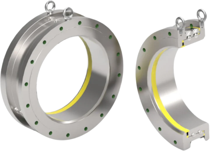
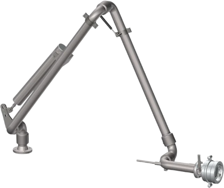
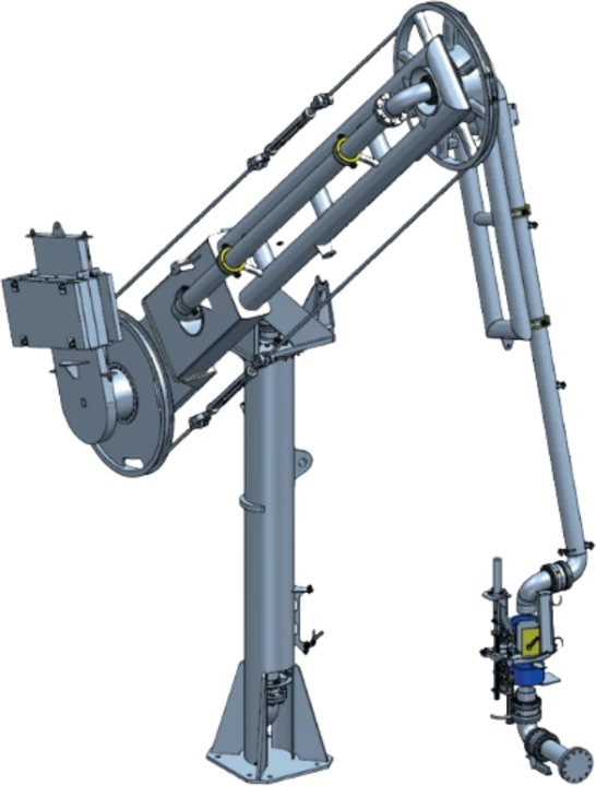
This edition focuses on servicing your 4″ safety breakaway coupling, a standard component in our bottom loading arms, and part of the wider MannTek range we distribute. Inspect couplings daily for dirt, seal, or physical damage. A full service should be carried out if the coupling is leaking, once a year as standard, or whenever the media being transferred changes. Service intervals otherwise depend on local rules and application conditions.
For new applications with unknown parameters, initial service after one year is recommended, adjusting further intervals based on inspection results. The service procedure itself consists of exchanging seals, then replacing any worn or damaged components. You’ll need the correct MannTek spare part kit and O-ring kit for your coupling size, only original MannTek spare parts should be used.
Before you start:
Before starting maintenance, depressurise the system and clean the parts. Wear protective goggles and avoid handling O-ring seals that look charred, gummy, or sticky.
Use tweezers and wear neoprene or PVC gloves. Avoid touching adjacent parts with bare hands. Rinse the parts again before beginning the “daily inspection.”
Disassembly Process:
After the coupling has released and servicing is required, there is a danger that fluid could still spurt out, which is why special protective equipment is needed. Here are the steps for maintenance:
Step 1: Unscrew and remove the damaged breaking bolts, and check the remaining parts for wear and tear.
Step 2: Remove the flat seal (if available) and unscrew the three screws that lock the spindle steering. Press down the spindle steering and turn it free, releasing it carefully as it is spring-loaded.
Step 3: Take out the spindle steering, spring, body, piston, spring cap, and PTFE-bushing from the coupling body.
Step 4: For the Piston O-Ring, replace the O-ring (pos.3) on the piston with a new greased O-ring, ensuring equal pressure around the O-ring. Press the O-ring into the groove on the piston using grease suitable for O-ring material. Use original MannTek spare parts only.
Step 5: For the Inner Body O-Ring, remove the nine screws and detach the coupling flange from the body. Replace the O-ring (pos.19) on the body with a new greased O-ring. Use only grease suitable for the O-ring material. Reattach the coupling flange to the body using Loctite® 243 on the nine screws. Tool: Allen key, 4 mm.
Step 6: For the Mounting Piston, introduce the piston into the valve seat as shown, ensuring it’s in a relaxed position. Take care, as the piston may protrude on the other side due to its larger diameter than the three brackets for the piston guide.
Once one half of the coupling has been fully disassembled and serviced, repeat Steps 1 to 6 on the second half.
Reassembly Process:
Step 1: To reassemble the coupling halves, fit the spring with spring cap and spindle steering with PTFE-bushing. Press down the spindle steering and turn to fix it in position.
Step 2: To lock the spindle steering, fit the screws into the given holes in the body and fixate the spindle steering by mounting the three locking screws. Use Loctite® 243 for locking the screws. Mount back the flat seal.
Step 3: When replacing any spare parts, using original MannTek parts is necessary. For the breaking bolts, screw them into position by hand only, without tools. Breaking bolts are precision-engineered, sensitive components, and any deformation from over-tightening will change their breaking parameters and compromise the coupling’s protection.
Step 4: Set both halves onto each other and press them carefully together, using a press if available to make this easier. The breaking pins should align to the bore holes in the second half. Screw on the nuts by hand until stop when the halves are pressed together. Fasten a little with a wrench, max 45 degrees. Screw on the second nut and lock the first one. Hold the first one with a wrench to avoid transferring force onto the breaking bolt. Tool: standard wrench, 10 mm.
Step 5: Before returning the coupling to service, carry out a pressure and tightness test on each half separately, in accordance with EN12266, EN14432, and ISO5208, and in line with the maximum test pressure specified for your coupling size in the MannTek service manual. This step is mandatory after every service and should never be skipped, even if the reassembly appears correct.
Take a look at the video down below to see it in person:
[vc_video link=”https://www.youtube.com/watch?v=oBnUvVBBWFY” align=”center”]
Following all these steps above should leave you with a good as new Safety Breakaway Coupling. If you have any questions about the above, then please get in contact with our sales team who will be more than happy to assist you.
